
⚡ Quick answer
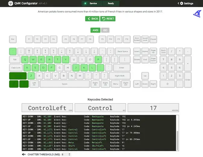
To test a keyboard PCB, plug it into your computer, open a key-testing tool (VIA, the QMK Configurator test matrix, or a browser tester like keyboardchecker.com), and short each switch footprint’s two pads with metal tweezers. Every position that registers on screen is good; any that stays silent has a hardware fault. The walkthrough below covers the switches, the microcontroller, the LEDs, and the USB connector, then how to fix what you find.
Whether you are building your own keyboard or troubleshooting one that started dropping keys, a few minutes of PCB testing saves hours of frustration later. The PCB is the backbone of the board, tying every switch and component together, so a single bad joint or trace can take out a key, a row, or the whole thing. Testing early tells you exactly where the problem is while it is still easy to fix or return.
What you need
- The keyboard PCB
- A USB cable
- A computer
- A key-testing tool: VIA (usevia.app) or the QMK Configurator test matrix for programmable boards, or a browser tester such as keyboardchecker.com for any board
- A conductive object: metal tweezers, a paperclip, or a small screwdriver
- A multimeter set to continuity mode (optional, for tracing dead spots)
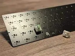
Work on a clean, static-free surface and take a moment to look over the board first. Knowing where the switch pads, diodes, and microcontroller sit makes it much easier to spot anything out of place while you test.
How a keyboard matrix works (and why it matters)
Before you test, it helps to know how the board is wired. Keyboards do not give every key its own wire to the controller. Instead the switches sit on a grid of rows and columns, and each key is the crossing point of one row and one column, with a small diode to stop ghosting. The controller scans the grid many times a second to see which crossings are closed.
This is why faults come in patterns. One dead key is usually a local problem at that switch. A whole row or column going dead at once points to a single shared trace or diode, not a dozen failed switches. Reading the pattern tells you where to look before you touch a soldering iron.
Step 1: Test the switch positions
The switch positions are the most important thing to check, since they register every key press. You can test them on a completely bare PCB, no soldering required.
- Connect the PCB to your computer with the USB cable.
- Open your key-testing tool and, if prompted, select the layout that matches your PCB.
- Take your metal tweezers or paperclip and briefly bridge the two pads for one switch position.
- Watch the screen. If that position is good, the tester registers a key press.
- Repeat for every switch position on the board.
If a position never registers, you have found a fault at that spot. On a hot-swap PCB you can also test by pushing a known-good switch into the socket instead of bridging the pads, which is often faster and more reliable than the tweezer short.
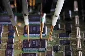
Step 2: Test the other components
Once the switch matrix checks out, confirm the rest of the board is healthy.
- Microcontroller: with a multimeter, measure the voltage across the VCC (power) and GND (ground) pins. A reading close to the expected value, usually around 5V or 3.3V, means it is powered correctly.
- LEDs: power the board and check that any indicator or per-key LEDs light up as expected. Dead LEDs point to a bad solder joint or a faulty LED.
- USB connector: plug the board into your computer and confirm it is recognised as a device. If nothing appears, the connector or its solder joints are the first suspects.
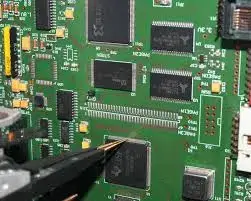
Step 3: Troubleshoot what you find
When a position or component fails, the fix depends on the pattern of the fault. This table covers the faults you will actually meet.
| Symptom | Likely cause | Fix |
|---|---|---|
| One dead key | Cold solder joint or cracked diode leg | Reflow the joints, check the nearby diode |
| Whole row or column dead | One shared broken trace or diode | Trace the row/column with continuity mode, find the break |
| Board not detected | USB connector or controller solder joints | Reflow the USB and controller pins first |
| Dead LEDs only | Bad LED joint or faulty LED | Reflow, then replace the LED if needed |
| Key registers twice | Missing or backwards diode | Check diode orientation and reseat it |
Always unplug the board before reworking joints, and take basic anti-static precautions when handling the components. If the part itself is damaged rather than just badly soldered, it may need replacing, which calls for careful soldering or professional help.
Extra tips
- Test in a logical order. Work row by row so you never lose track of which position you just checked, especially on a full-size board.
- Not sure about a single key? Bridge its pads again and watch closely. A position that registers intermittently usually has a marginal solder joint worth reflowing.
- Use the multimeter for the stubborn faults. Continuity mode between a switch pad and the microcontroller side quickly reveals a broken trace that a key tester alone cannot pinpoint.
💡 Building a board from scratch? Test the bare PCB before you solder or seat a single switch. It takes ten minutes and catches faults while they are still easy to fix. See our custom keyboard build guide for where this fits in the full process.
Frequently asked questions
When should I test my keyboard PCB?
Test a bare PCB before soldering switches or assembling the case. It takes ten minutes and catches faults while they are still easy to fix or return. Re-test after any modification, and whenever keys start misbehaving.
Can I test a keyboard PCB without soldering it?
Yes, that is exactly what the tweezer test does. Shorting the two switch pads with a conductive tool simulates a key press, so you can verify every position on a completely bare PCB. Hot-swap PCBs can also be tested by pushing switches into the sockets.
What should I do if some keys do not register during testing?
Check the solder joints and traces around the dead key first, and use a multimeter in continuity mode between the switch pad and the microcontroller side to find the break. If a whole row or column is dead at once, the fault is usually a single shared trace or diode rather than the individual switches.
Which software tools can I use for PCB testing?
VIA (usevia.app) has a built-in key tester and runs in the browser for VIA-enabled boards. The QMK Configurator offers a test matrix for QMK boards. For anything else, a generic browser tester such as keyboardchecker.com shows each registered keystroke.
Do I need to test a pre-assembled PCB?
Yes, briefly. Factory QC misses things, and shipping can damage solder joints. A two-minute full-key test on arrival keeps you inside the return window if something is wrong.
Why does one of my keys register twice?
A key that fires twice or chatters usually has a missing, damaged, or backwards diode at that position. Check the diode orientation against a working key, reseat or replace it, and reflow the joint.